NHR-3 – Bone Roll
Free PreviewBone rolls values are extremely important to let the rig work correctly during animation. Having a clean and consistent bone setup with correct bone roll settings also avoid tedious and sometimes almost impossible fixes.
The correct bone roll settings are also important for animators because one of the major interaction models for transforms is via hotkeys, using the x, y, and z keys to specify axes. And finally a well organized setting of bone roll can make manual animating easier when we use Blender’s pose tools for copy&paste and copy&mirrorpaste.
One major aim of this course is also to give you knowledge at hand that allows you to understand what Avastar does under the hood. Thus we are looking behind the curtain instead of just telling you about magic buttons and cook book solutions. So be prepared to get into some details.
The course is separated into 7 lessons. This is lesson 3 (updated for Avastar-1.2)
Content of Lesson 3:
- The local Y Axis
- The Dominant Axis
- The Lower Arms (Elbow Joints)
- The Lower legs (Knee Joints)
- The Head
- The Eyes
- The Dominant axis and the X-Z Plane
- Enable Axes Display
- Bones with 2 dominant axes
- Which axis to use when ?
- Modify the Bone Roll
- Editing the Avastar Rig
- Adjust the wrist Bone
- Left-Right symmetries
- Create a symmetric Pose
- Fixing Bone roll Asymmetry
- The root Bone
- The COG Bone
The following description is about how you would setup a rig with left/right symmetry as we have for example for the human skeleton or for the horse skeleton.
The local Y Axis
In Blender every bone has its local Y axis always aligned along the bone’s longitudinal axis. And since in Blender all bones always have a length, the longitudinal axis of a bone is always defined. So we see the local Y-Axis is completely determined by the bone’s orientation.
But we also have to set the X-axis and the Z-axis. All that we know for now is: The X-Z axes define a plane perpendicular to the bone’s longitudinal axis (see image). But we are free to rotate the X-Z axes around the Y axis of the bone as we like. This angle of rotation is the bone roll…
So what next ? In the following Lets only look at the remaining 2 axes (X and Z) and see how we have to adjust these axes (how to set the Bone roll).
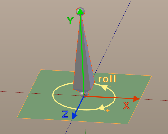
The “Bone Roll” is a rotation angle. It determines the relative rotation of the bone’s local X-Z plane around the Bones longitudinal axis. The Bone Roll value range is [-360°,+360°]. For more about Bone roll see further down.
The Dominant axis
Before we modify the Bone roll values let us first take a look into how the particular skeleton is supposed to work. For example we recognize quickly that most bones have one axis around which the bone will rotate naturally. This axis is called the “Dominant rotation axis”. Lets look at an Avastar model in T-Pose (just because it is easy to understand the principles, you can use any rig you like, the following remains valid).
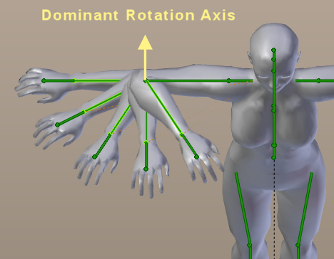
The Lower Arms (Elbow Joints)
The lower arms can only rotate along one single axis in relation to the upper arm. Try it out on yourself in front of a mirror. You see immediately that the lower arms have only one rotation axis relative to their parent bone (the upper arms). And this axis points upwards when the character is in T-Pose (see image)
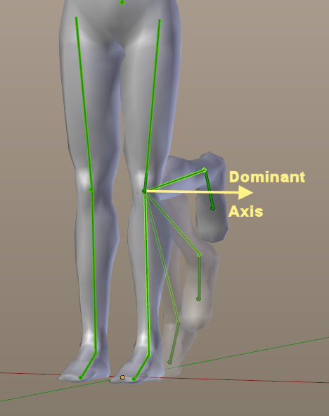
The Lower legs (Knee Joints)
The lower legs can only rotate forward/backward. At least that is how the lower leg is supposed to work. Try to bend it sideways. No chance…
Hence the Leg’s dominant Axes point sidewards in this case.
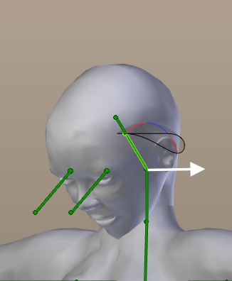
The Head:
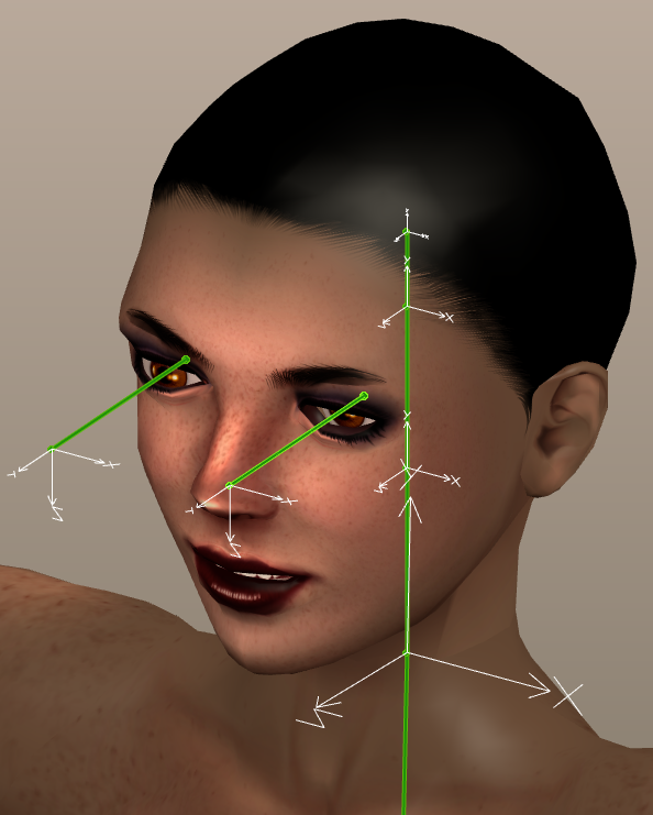
The head is good for nodding (the ‘yes’ gesture, see image) But try to “nod sideways”… That works but it is not easy and the angle of rotation is only small compared to the “yes” gesture.
So for the head the dominant axis goes sidewards.
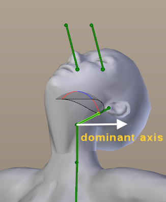
Sidenote: The head (and many other bones as well) also can rotate along its local Y axis (the “no” gesture). But we only look at local X and Z when it comes to Bone Roll. So we can ignore rotations around Y for now.
Actually we have cases where we can not clearly tell the dominant axis, like for the eyes which can rotate naturally on 2 axes. The Clavicle bones (Collar Bones) is another example. For these bones we have the freedom to choose which axis we take as the dominant axis.
The Eyes
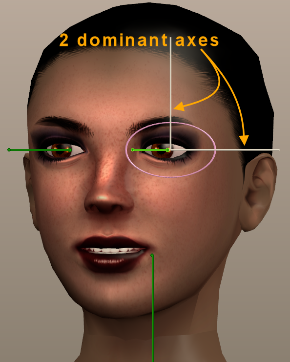
The eyes have 2 rotation axes (for rolling eyes). In this case you are free to choose the dominant axis to your likes. Well, you could flip a coin or think of something consistent with the neighborhood… But see below.
From the image we can see the dominant axis could be chosen to go sidewards (if we want eyes up/down to be the dominant movement). Or we can set the dominant axis upwards if we want eyes right/left to be the dominant movement.
The dominant axis and the X-Z plane
It is always good to keep things consistent and easy. Therefore one (the) advise is to align either the bone’s Z axis or the bone’s X Axis with the dominant rotation axis. Actually the choice of X versus Z axis as the “dominant” rotation axis is arbitrary. What matters here is consistency within the rig (or within the project if it’s a larger project). So in principle you take your choice (X or Z) and then keep with that choice for the entire skeleton. However we have learned in the previous chapter that the BVH standard imposes some rules regarding the local bone axes. So we will keep with these rules.
Enable Axes display
You can enable the display of local Bone axes from the Armature’s Data Properties window. Ensure that the “Axes” Option is checkmarked.Please note that the local bone axes are displayed at the bone tail and not at the bone head:
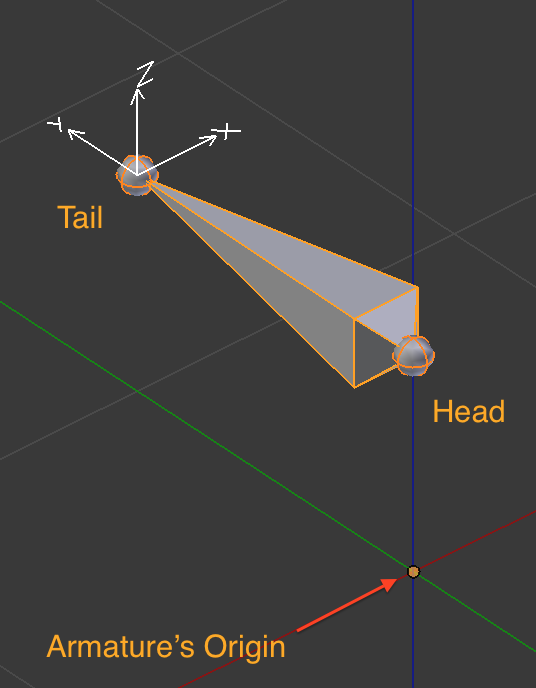
Local axes are visible in Edit mode and in Pose Mode
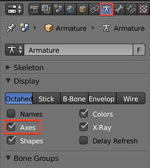
How to enable the Axes display
One reason for displaying the local bone axes at the bone tail is that you can have multiple bones having the same parent. In that case it is beneficial to have the local bone axes be attached to the Bone tail. Because otherwise the local axes of all siblings would be drawn “into each other” and thus would no longer be readable.
Let us assume you have decided to always align the bone’s local X axis to the dominant rotation axis. Then regardless of which bone is animated, you (or your animator if you work in a team) can assume that any bone’s local X axis will be the “typically used rotation axis” (just because you had organized the rig like that!)
When you follow this rule, then you do not have to think over and over again which axis to animate, which FCurve to look at, etc… So your rig is nicely setup and easy to use. And your animator(s) will love you!
Bones with 2 dominant axes
Ok, now sometimes the dominant axis is not clearly determined (like in the eyes example above). In this case you will have to take a decision (flip a coin maybe). However, in most cases you can find something better by comparison with the neighborhood. So lets take another look at the eyes:
One “solution” here would be to look at the eye’s parent bone, the head. And then use the same alignment on the eyes. This is exactly what i did in the image above. So for the head all bones dominant axes point sidewards and are aligned to global X.
And while we are it it, we now can walk down along the spine and check the dominant axes of each spine bones. It turns out that all spine bone’s dominant axes have the same orientation (see image to the right). So in this case the entire spine from the pelvis up to the skull has a consistent axis orientation. And this is easy to remember.

Dominant bone rotations assigned to X (Click to zoom in)
“In this rig the dominant axis is aligned with the bone’s local X axis. And the dominant rotation axes of the spine and the entire head point sidewards”
So in general we have to determine the dominant rotation axis for each joint (in blender joints correspond to the bone heads) and then align the X- or Z- axis of the bone to the dominant axis. However there is also the BVH standard that imposes “for horizontal bones align the local Z axis with global UP axis” so we might want to align the eye bones with Z pointing upwards rather then downwards.
You see again, it is more about consistency than about strict rules…
Which axis to use when ?
As noted before you can decide to adjust either local Z or local X to your dominant axis. But there is a small caveat here. Lets look at the arms of a simple human armature.
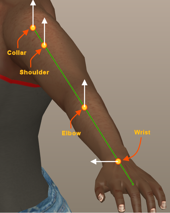
the arms contain 4 joints:
- Wrist (the hand bone)
- Elbow (the lower arm bone)
- Shoulder (the upper arm bone)
- Collar (the Clavicle)
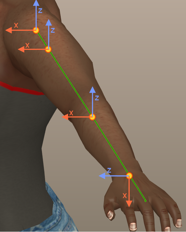
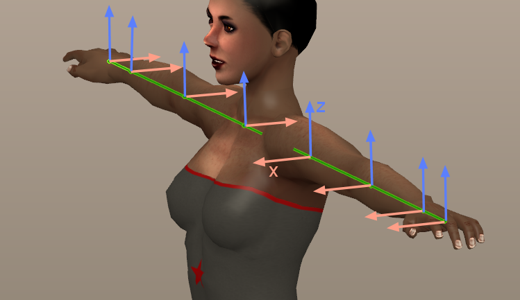
Then we find for the dominant axes (see image):
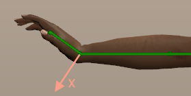
- Wrist dominant axis points forwards
- Elbow dominant axis points upwards
- Shoulder dominant axis points upwards
- Collar dominant axis points upwards or forwards (dominant axis not determined)
Modify the “Bone Roll”
Ok, lets decide to make the collars dominant axis the forward/backward axis. Then all bones (except the wrist) have their dominant axis point upwards (see white lines in the image).
Now it is time to learn how we actually can align bone axes to their dominant rotation axes. You might have already experimented a bit and probably you have detected, that we can not align the X-Z axis by simply rotating the bone around the Y axis. That does not work in edit mode. Nothing happens when you try to do that. This rotation of the X-Z axes is actually done with the Bone roll…
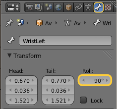
The Bone Roll can be modified only when the skeleton is in edit mode. Then you find the Bone Roll field in the Armature’s Bone properties.
Hint: As an alternative you also can use CTRL +r and change the bone roll by dragging the mouse or enter a number (rotation angle).
Please remind: You also can display the bone’s local axes. You do this by enabling the “Axes” option in the Armature’s data Properties window (see the “enable axes display” toggle box further up in this lesson)
Important for Avastar Users
Editing the Avastar Rig
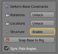
Adjust the Wrist Bone
Now lets align the bone Z axes to the dominant axes by adjusting the bone roll of the bones as needed. Actually most bones do not need to be adjusted. We only need to edit the wrist bone’s Roll. And there a value of 90° seems to do what we want.
Then all looks good. But see that for the wrist the local X-Z plane has now also been rotated by 90° compared to the other 3 bones in the arm.
Furthermore the alignment of the dominant axis to the bone Z axis can be done such that (for the wrist) the Z axis points forward OR backward. We have chosen to align it to point forward. And this will become important when we look at …
Left-Right symmetries
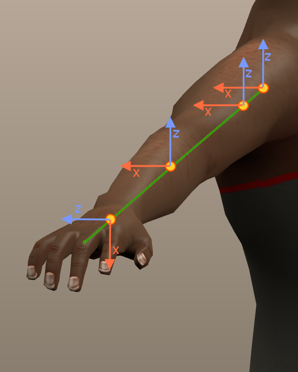
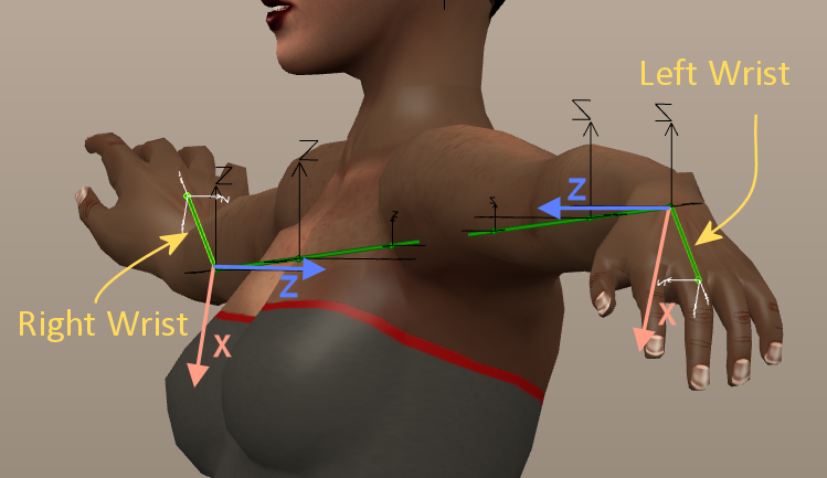
Lets move ahead to the other arm and try to achieve exactly the same bone axis alignment. We find there is no way to align the axes in the “same way” (Z up and X forward). This is because of the mirror symmetry of the skeleton.
First we notice that when we want to keep Z point upwards, then all X axes now point backwards. On the other arm we had X axes point forward.
Then on the wrist we see that we can either keep X pointing downwards, or we can keep Z pointing forward. I have chosen to keep the X axis pointing downwards. This can be achieved by setting a Bone Roll of 90° for the other wrist as well.
But this is a bad choice and in first place it is not at all apparent that we made something more complicated than it needs to be. Lets make an experiment to see the problem…
Create a symmetric pose
Lets create a pose that is symmetric on the right and left arm. we will only concentrate on the wrist for now.
- Ensure that you are in Pose mode
- Go to Front view
- Select one wrist and rotate it by some degrees around the (global) Y axis
Remind we have aligned the bone’s local Z axis to its dominant rotation axis, which points to positive Y in the scene. Well…
- Now copy the pose to the copy buffer
- And finally Mirror-Paste to the other side
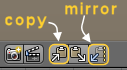
Note: The Pose copy and mirror paste functions can be found in the footer of the 3D Viewport.
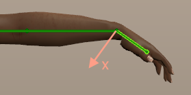
Now you expect the wrist to bend in the same way on both sides. But actually where the wrist bends down on one side, it bends up on the other side. Not good!
Fixing Bone Roll Asymmetry
The reason why this happens is buried in the mirror paste function. Actually you can see right away that we have chosen a Bone roll of 90° for both(!) wrists so that the bones X-axis points downwards for both wrists.
But apparently the mirrorpaste function assumes that the rotation angle goes in the opposite direction.
Click to Zoom in
Thus we need to let the local Z-axis to point into the same direction for both bones. Thus one wrist needs a roll of 90° and the other wrist needs a roll of -90°.
Click to Zoom in
However…While this approach works technically, it leaves us with a somewhat asymmetric bone roll setting on the wrists:
- right wrist: local X points upwards, local Z points forward
- left wrist: local X points downwards, local Z points forward
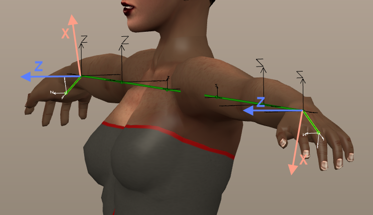
While the axes for all other bones all are aligned with Z pointing upwards. This looks a bit unclean. But remember, we still could try to align the dominant wrist axis to the bone’s local X axis instead of using the Z-axis. So lets try this now and see how it differs:
- Assign the dominant axis of both wrists to the bone’s local X axis (instead of the Z-axis as we did before)
- Now the local Z axis points upwards for both wrists. (Modify the bone roll until the Z-axis points upwards)
- Now the local X axis points forward for one wrist and backward for the other.
Click to Zoom in
Now the skeleton looks much cleaner and appears to be more consistent. Actually you should remember this image showed up already in the previous lesson. this is exactly what the BVH standard imposes on the Bone axes (horizontal bones have their local Z axis aligned to the global UP axis). So we have now 2 good reasons for why Avastar uses this configuration as well.
Summary
By now you should have all basic knowledge to get your Bone rolls setup in a consistent way. There is no “one way to make it right”. You often have to decide on your own what is good and/or makes sense on your specific rig. But the general rules should be clear by now. Actually we can summarize all of this to:
- Decide to your likes, but ensure you keep things easy and consistent!
- If BVH compliance is wanted, then apply the BVH rules of thumb (horizontal bones: Z-UP vertical bones: X-SIDEWARDS as explained in the previous chapter)
And now we are ready to step into “horse making” work without fearing to mess things up.
Preview on next lesson
After the previous chapters have taken us through a bit of theory and history, now we will proceed with some practical work.
In this lesson we will start with the default Human skeleton and bend it “into” a Horse skeleton. This approach is dictated by the limitations imposed on us by Second Life. We are obliged to reuse the Second Life Avatar’s skeleton as it is. We only are allowed to move the joints around. However we will see that we can get very close to a reasonable Qudruped skeleton that also would work for almost any other quadruped as well…
just because it is easy to understand the principles, you can use any rig you like, the following remains valid
At what point in this process do we bind the creature mesh to the armature?
Any time after you have finished editing your armature.