NHR-6 – Fixing IK Targets
Free PreviewThe last thing to fix is the IK target locations: The IK targets have been fitted to the Avastar human character. But after we changed the Skeleton to a Horse skeleton the IK bones no longer are where they should be. Actually they MUST be placed where the hoofs are, otherwise the animation process would be incomplete:
One major aim of this course is also to give you knowledge at hand that allows you to understand what Avastar does under the hood. Thus we are looking behind the curtain instead of just telling you about magic buttons and cook book solutions. So be prepared to get into some details.
The course is separated into 7 lessons. This is lesson 6 (updated for Avastar-1.2)
Content of Lesson 6:
- Snap IK Bones to Rig
- Manual Process
- The Pole Angle
- Rotation Constraints
- IK Rotation limits
- FK Rotation limits
So lets go ahead and match the IK Targets to the Horse skeleton. To do so, the easiest way is to go into Pose mode, the animation tools provide a very useful operator that will make us save tons of extra work to accomplish this task (and actually we visited this tool already in the previous lesson):
Snap Base to Rig
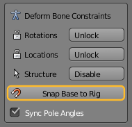
The Snap Base to Rig tool automates what would otherwise be a tedious and time consuming task: Adjusting the IK Bones to match the Rig. You find the tool in the Tool Shelf, in the Deform Bone Control panel when the Armature is in Edit Mode.
- So ensure you are in Edit Mode
- Open the Tool Shelf
- locate the Constraints panel
- Now call Snap Base to Rig
Note: For Avastar-1.0: This was a separate tool named Snap IK Bones to Rig. However the overall behaviour was exactly as described here.
The tool Operator (Avastar-1.1)
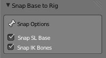
Note for Avastar-1.0 users: When you only enable the Snap SL Base option, then the tool behaves like the old Snap SL Bones to Rig tool from Avastar 1.0. And when you only enable the Snap IK Bones option, then the tool behaves like the old Snap IK Bones to rig tool.
Under the covers
The Snap Base to Rig tool works quiet nice for our horse model. However it may be possible that you have to setup things manually for example when the IK bones are used in an unusual way. For this case we have created a very detailed section about fixing the ik bones manually. We strongly recommend that you visit this section as well. You will get a much better understanding of how the ikBones work and what the Snap IK bones to Rig actually does for you.
Optional: The Manual process
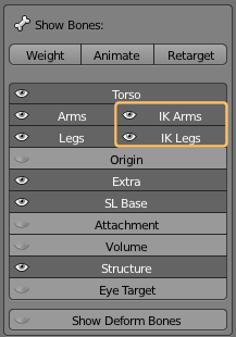
The first task is to enable the IK bones display:
- In the Object Data properties (Stick man icon) locate the Show Bones Panel
- There enable the IK Arms and IK Legs so that the bones become visible.
Note: We have 2 Arm IK Bones and 2 Leg IK Bones. You might want to disable all other bones for a moment so that you can see only the IK Bones. (next image)
Avastar-1.2: This has been automatically fixed when you called the function “Snap Base To rig” from the Constraints Panel in the Tool Shelf. So the IK Bones are most probably already where they should be.
However in some cases the automated alignment may fail. So the following description might still be of value.
Auto Align the ik Bones
The IK Bone control panels are all located in the Properties sidebar of the 3D View (Open the Properties sidebar by pressing the ‘N’ key while the cursor is in the 3D View.
For Avastar 1.0: Please select at least one IK Leg bone and one IK Arm bone in the 3D View. Otherwise the IK controls do not show up (or show up only partially)
In the Rig Display panel -we already used this earlier- we can find some buttons that will help us in this task as said above.
- Locate the sub panel Target Align
- Now you either just click on the function “Align IK to Pose” (Avastar-1.1)
- Or you open the sub panel by clicking on the small plus (+) icon and proceed…
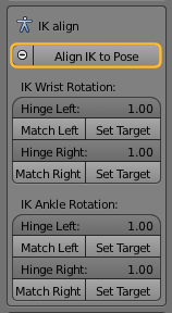
Locate the sections named IK wrist Rotation and IK Ankle Rotation.
Hit the buttons “Match Left”, “Set Target”, “Match Right” and its “Set Target” under both Wrist rotation and Ankle Rotation sections.
What these operators do is to snap the ik Bones to their related Control bones. In detail they perform following operations:
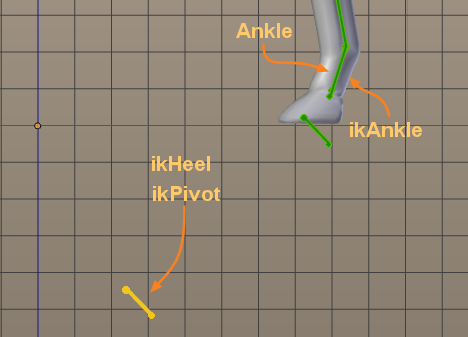
- Snap ikAnkles to the Ankle bones
- Move ikHeels as if they are clamped to the ikAnkles.
- Snap ikPivots to ikHeels
- Snap ikWrists to Wrist bones
The Match works perfectly for the wrists and the ankles. But for the heels and the pivots we need to do a manual correction. So we will need some manual fixing for the ikHeels and ikPivots.
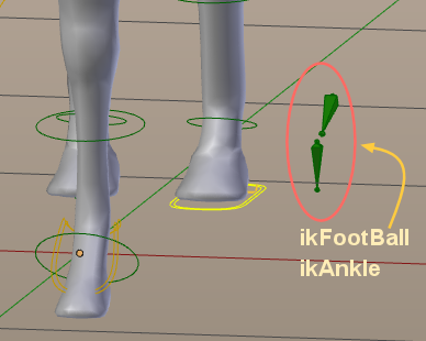
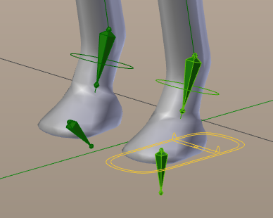
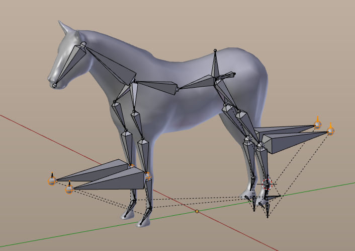
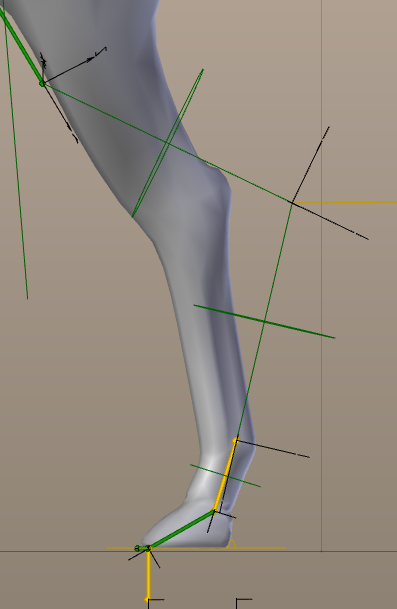
Foot bones before & after matching
You can clearly see the ikHeels are offset from the legs (still at their original position for the human shape). And there is a mismatch between the Ankles and ikAnkles.
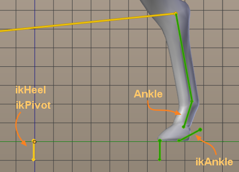
Note: The ikFootBalls have been rotated as well. We will ignore this for now.
From here we can proceed in 2 ways. We can use Avastar’s “Snap Rig to Pose” tool, or we can keep on with manual editing and fix the bones manually in edit mode. I personally think that using the snap tool is a little more convenient. But doing it all manually in edit mode again helps you to understand the topic in much more detail. Take your choice (actually we encourage you to work through both options!):
The short way (Fix in Pose Mode)
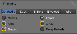
Hint: While we are there already i’d like to remind you that you also can set the axes visibility here and control the x-ray mode.
You end up with something like shown in the image.
You may have noted that the two ikBones for Foot and Ankle now have moved out of place. So select them and move them back to their place.
So far we have been working in Pose mode. And this means all our modifications will be reset as soon as we go to rest pose. Now the goal is to copy the left foot pose to he right foot, and then propagate our pose into the skeleton in edit mode.
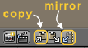
Copy the pose to the other side
Pose mode allows you to cut and mirrorpaste a pose. All you have to do is
- select the 4 foot bones ikHeel, ikPivot, ikAnkle and ikFootBall.
- Cut the bones into the copy pose buffer.
- And finally Mirror paste:
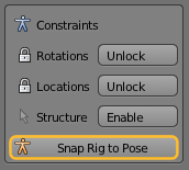
Now we only have to propagate our pose to the edit bones. This is done with the “Snap Rig to Pose” tool as shown next.
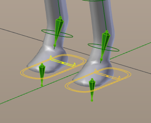 Now the foot bone pose has been mirrored to the other foot.
Snap Rig to Pose
Now we have fixed the major part of the Skeleton to be used with the ik bones. You might think this is a lot of work just for fixing the ik bones. But this will pay back as soon as you are going to animate your character.
The long way (Fix in Edit mode)
Here is how you can help yourself when you have no extra tools available or when you are curious and want to learn what the “Bake to Rest Pose” tool from Avastar really does for you.
Manual fixes in edit mode
Now we are ready go back to Edit mode. The IK Heel bone and the Foot Pivot bone are fully overlapping in Edit mode. Right click on them once or twice until the IK Heel bone is the selected one.
You can see the name at the bottom left hand side of the screen:
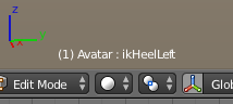
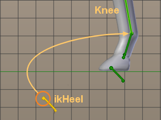
We now have to align these bones to the rear Shin bones (Knee Bones) of our character.
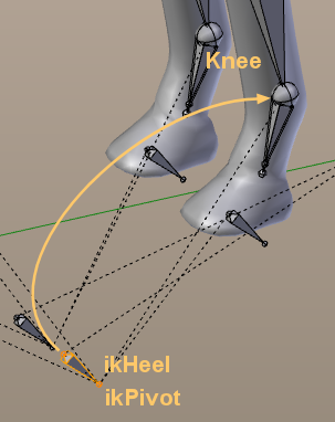
ikHeel and ikPivot overlap (intentionally)
Move the ik Heels into place
Note: as before you only need to move one of these bones. The symmertrical bone will follow automatically (due to the x mirror setting)
- Go to edit mode
- Select the tip (tail) of the Knee bone (1)
- Armature -> Snap -> Cursor to Selected (SHIFT +S)
Now the Cursor is aligned with the tip of the Knee Bone
- Select the head of the ik Heel (2)
- Armature -> Snap -> Selection to Cursor
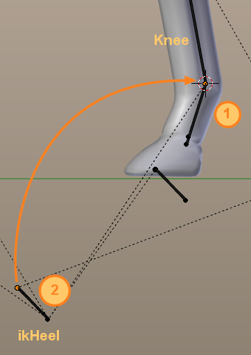
Now the head of the ik bone is snapped to the tail of the Knee Bone.
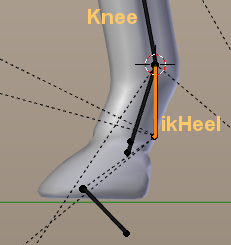
- Select the Tail of the ik Heel
- Move the tail “under” the head, such that the bone tip points to the ground:
After you have moved the ikHeel bone, proceed by moving the ikPivot bone into the same location as the ikHeel.
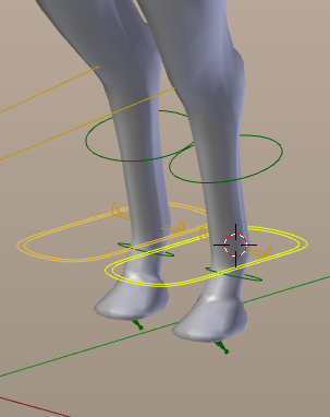
Now, if we go into Pose mode and enable the Custom shapes again for the bones, then we should see something like in the image to the right: The ikHeel bones are hovering above ground.
This is wrong, but the fix is easy:
- Go back to Edit mode
- lower the heels Head to the grid floor (z=0 in our case).
Do this best in Side View (NUM_PAD 3)
Now if we switch again back to pose mode, the IK bone is where it should be: laying on the floor. The foot pivot bone should overlap the IK Heel controller, so just repeat the process we just did. This time we do:
- snap the 3D cursor on the upper side of the IK Heel bone.
- Select the Foot Pivot’s head
- And snap it to the 3D cursor.
All is well and perfectly working now!!
However you decided to proceed, at the very end of your work you will have to …
Fix the ik Targets
This is an easy task, it’s only a matter of snapping these bones to the knees and elbows (actually this is already correct in our case), and move them to the same direction in which they are supposed to bend.
Click to Zoom in
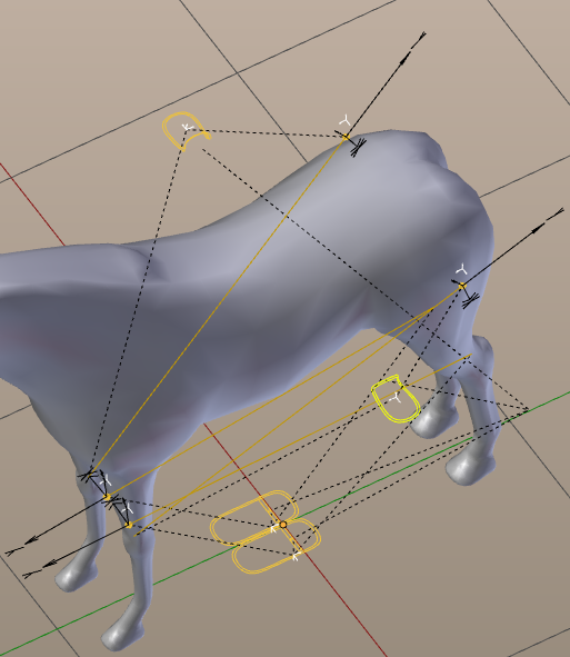
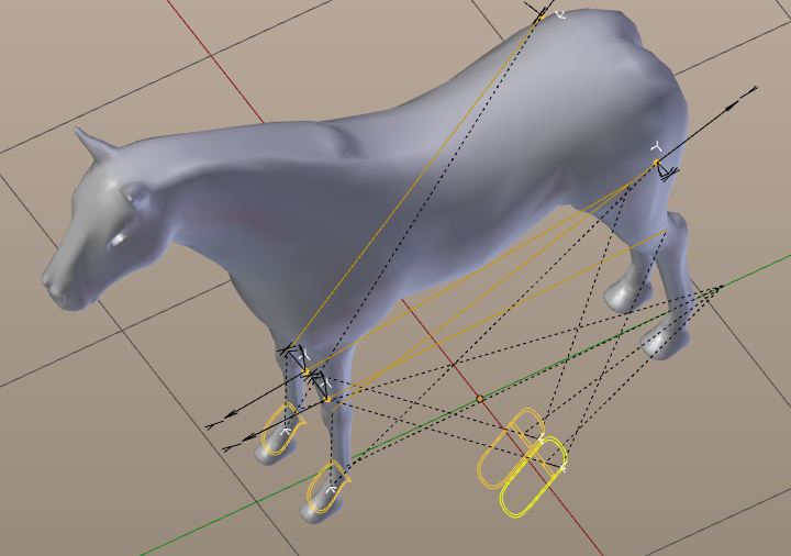
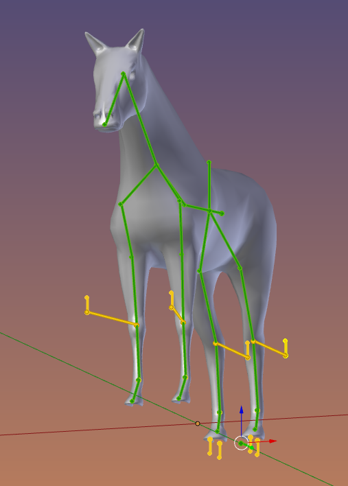
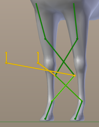
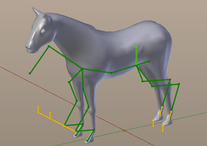
Your result will look something like this when you go to Pose mode and enable Custom Bone Shapes:
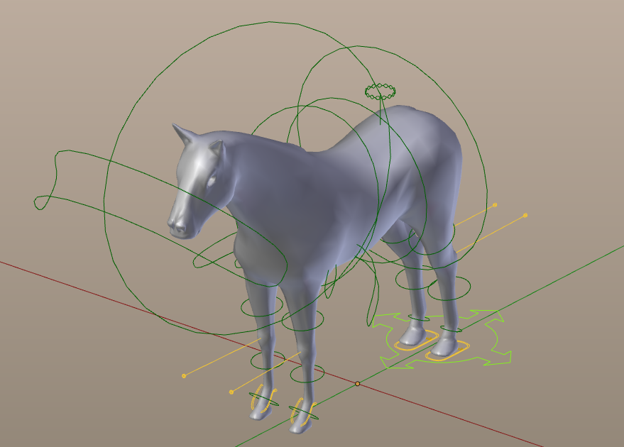
The model after ik bones have been fixed
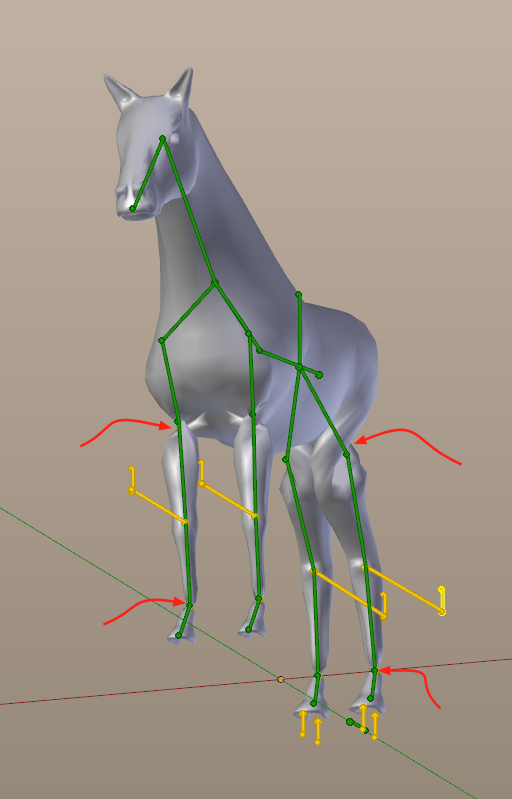
Note that the ik Targets of the rear legs point backwards, while the ik targets of the front legs point forward. this will give us some more hustle. So we are not yet at the end. But since everything looks like it is setup properly, let’s check how the modified IK Bones are working for us.
The Pole Angle
Avastar 1.0
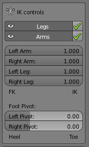
Go ahead and enable the IK from the Rig Properties panel in the right properties sidebar:
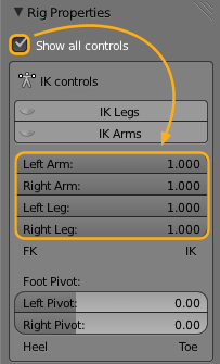
Look what happens while you set all of them up to 1.0 (see image) Now the legs and arms get distorted. Why this ?
Click to Zoom in
Avastar 1.1
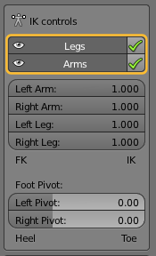
Please enable the visibility AND set the checkmarks as indicated in the image above. Nothing should have changed on your model. However sometimes it may be possible that you get distorted legs or arms.
Since we moved the ik targets from their previous positions, we need to fix some constraints settings to match the new shape. And the property that we will have to change is the “Pole Angle”:
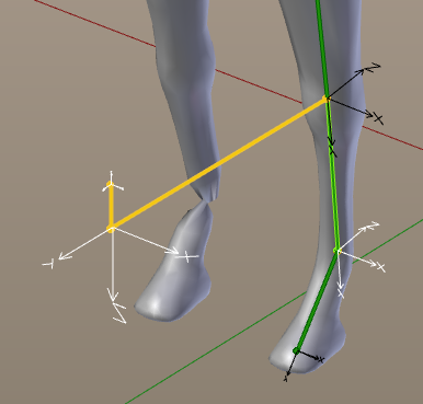
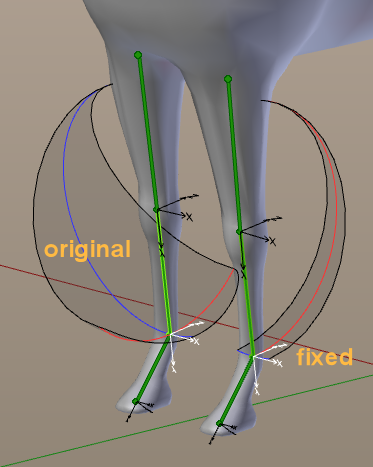
When you move the pole target around the limb, then the corresponding bone will rotate. And since we have actually rotated the pole targets by about 180°, now the limbs are turned around in the wrong direction.
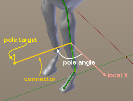
The pole angle is actually a fixed value. You can calculate the angle by finding the angle between the local X axis of the affected bone and the connection line from the bone to the pole target (see image above). But in Blender the pole angle is set manually. So when you change the location of the pole target, then the pole angle gets wrong.
In our case when looking at the image above we can conclude the pole angle is wrong by 180° after we have moved the pole targets to their correct position. So let us fix this now for all 4 limbs (one at a time).
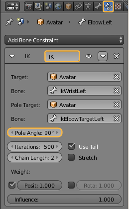
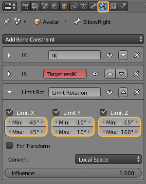
- Select the Elbow (or Knee bone)
- Then open the Bone Constraint panel (see image)
- and locate the IK Bone constraint that has the correct Pole target specified. (e.g. for the left elbow the pole target is “ikElbowTargetLeft”)
The slider labeled “Pole Angle” is what drives the current misbehavior. It is currently set to +90°, while the front knee is turning the wrong way around. Let’s try to change this value to -90°, and we’ll see the knees turning the direction in which they should be pointing.
And as soon as we do this, the limb distortions are gone!
You have to apply similar fixes on all other knees and elbows. And note: on the rear legs the pole angles need to be changed from -90° to +90°.
Rotation Constraints
Final check: with IK enabled, drag the COG bone downwards and watch the legs reaction. If they look like the next picture, all was done correctly. So far all is well for the rear legs…
So lets turn our attention to the front legs. But wait, on the front legs something’s wrong: They are bending the wrong direction…
Calm down and relax, it’s all under control. Remind that this horse has been bended from the default Avastar shape into the current horse shape. And we have rotated the arms to reuse them as the horse’s front legs. And… there are other IK constraints delivered from Avastar which need to be fixed because they are made for a human rig…
Note: The constrained bones are the Elbow bones in this case. So you have to choose these bones (one by one) in order to proceed.
- Open the Bone panel in the Properties window: a button with a bone icon.
- Within the panel locate the Inverse Kinematics section
In there we can find rotation locks and guess what? On the misbehaving knees, there’s a lock applied on X and Y axis! Hence this bone is allowed to rotate ONLY on its local Z axis in this case. Indeed we can see that the front leg bends along the bone’s local Z axis which is wrong of course.
Instead we want this leg to bend along the X axis!
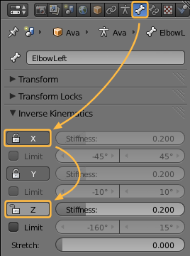
So… as soon as we disable the lock on the X Axis and enable the lock on the Z axis, then -Magically- the leg snaps to the right bending direction. Fix the constraint for both Elbow Bones…
And now the rig does what we want. But note: There are many more settings which can be optimized for your animation tasks. For example the…
IK Bone rotation limits
FK Bone Rotation limits
You only need to set the limits for the green control bones (if you want to use the limits at all on your rig). But be patient, its a lot of manual work. But it might help you later when you are doing your animations.
Rotation limits are all wrong. You can fix them in the Inverse Kinematics panel
We are now at the end of this chapter. This topic is admittedly a complex one. But i hope i could explain the concepts in a reasonable way and you can benefit from this knowledge in your future projects, when you start creating Octopus fish, Aliens, whatever …
Preview on next Lesson
In the next lesson we will take care of rigging the horse to the Armature and we will talk about a few issues with weighting.
We’re finally here! The skinning process is what defines how the mesh should deform to follow our skeleton’s movements. It’s the final, most important thing we have to do to be able to upload our newly created character to Second Life. Avastar provides quite a few options to help us in this process, but for the sake of clarity we also describe the manual process…
Hiya Gaia – these lessons are fabulous so far! – I must ask though, is there a function on avastar to snap the volume, and attachment bones to the non-human rig? I’m thinking ahead for adding things like a tail, and accessories, and with the possibility to be able to resize some of the final avatar.
–Edit – I manually moved each attachment bone to where I thought would be a sensibly place (taking care to keep it with its parent bone) and I found that in pose mode – if you select your newly moved attachment bone and press CTRL A a popup menu appears and allows you to ‘Apply Pose as Rest Pose’ – I’m hoping that when I import this rig, my attachment points will behave. Good fun to experiment though ^.^
Thumbs down 🙁
Would you mind to explain why you dislike this lesson ? Where is it bad to understand, what is missing, where is it wrong, etc… that could help us to make this lesson better.
thanks,
Gaia
it is not the lesson itself but seems that after I do everything i am at the same point did nothing but it is my fault cause i believed that i could do fishes horses like in the free video but now i realized that it has a long road before things gets concrete maybe i should forget all for a bit , but thanks anyway
It is true that this course topic is extremely complex. Actually we could easily blow up the course into the double size and still only scratching the surface. Just take a look at the course offers that you can get from universities and institutes. Animation courses typically go over 2-3 years. This might make it understandable that our course is not a cakewalk at all.
However i would like to improve the course to make it more useful and less frustrating. So if there is anything that could make you become more happy then please let me know. I dislike to just let you alone with frustration.
Hi Gaia – there is one improvement I might ask for, and that is if you could name the specific bones in each of your pictures with the actual Rig bones. The first rig I modified seemed to go well until I realised, I’d used hip links as hips instead of leaving them where they should be. It’s a stupid error on my part, but also an easy mistake to make when you are working from a picture and trying to guess which bone is which. XD