NHR-2 – The story of Bones
Free PreviewNow we have our Avatar ready to be edited, but before we start diving into horse making activities we need to take a more detailed look into how the SL Avatar’s Bone System is actually constructed.
You might be aware that the Second Life Avatar was originally created using Maya. Thus many of its properties result from how the Maya Animation System was implemented. That’s why we decided to add a small excursion into Maya to better understand the Bone orientations of the SL Avatar within Blender. And since Maya uses the BVH format for its animations we have to take a closer look at this as well.
One major aim of this course is also to give you knowledge at hand that allows you to understand what Avastar does under the hood. Thus we are looking behind the curtain instead of just telling you about magic buttons and cook book solutions. So be prepared to get into some details.
Content of Lesson 2:
- A bit of History about BVH
- The T-Pose
- Tools Differ
- Maya in More detail
- Proceed to Blender
- Adding a single Bone
- Show Bone Axes in Object Mode
- BVH again …
- Avastar’s Origin Bone
- Editing the Bone(s)
- Offset and Roll
- Bone Axes in Pose/Edit Mode
- Bone Transform Properties
- Transformations in Edit Mode
- The Bone Data Properties
The course is separated into 7 lessons. This is lesson 2 (works for all recent versions of Blender)
A bit of History
Back in 2002 Second Life was entirely designed with Maya. Maya was the first feature complete 3D animation software ever commercialized. That also included the availability of deform-based animation for polygonal mesh objects. Eventually Autodesk (the producer of 3DSMax at the time) bought Maya from its former owner Alias.
At this time all data related to animated 3D objects was built on Maya’s standards. And this included the usage of the hierarchical BVH data format which was basically designed to move animation data between different applications.
More about BVH
BVH is a shortcut for BioVision Hierarchy. This data format was invented by the meanwhile defunct company Biovision. The original purpose of this data format was to specify movements of human characters and thus a few assumptions where made in order to facilitate the creation and interpretation of the data.
You can get a brief information about BVH from UW-Madison Department of Computer Sciences. From this source we can read:
So in first place BVH imposed a specification for the Global (World) coordinate system:
- The global Y axis points upward.
- The global Z axis points forward.
- The global X axis points to the left (seen from character).
- The character always looks towards the positive Z axis when in rest pose.
Since BVH assumes the human’s natural rest position is with arms down, this implies that all bones of a simple human skeleton are pointing along the World Y axis.
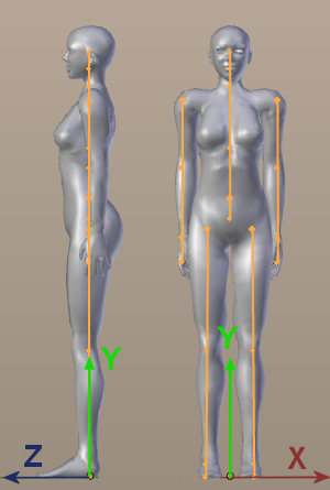
This has imposed following additional rules:
- All bones local Y-axes are aligned to the World Y axis.
- Hence all bones longitudinal axes match with their local Y axis.
- To keep it simple all bones local X axes (the white coordinate systems in the image) have been aligned to the Global X axis.
- And all local Z axes have been aligned to the Global Z axis
When you look into the details you will find that bones which point upwards (the spine bones) have their local Z axis pointing forward. While all other bones have their local Z axis pointing backwards.
And (to make calculations easier) the entire skeleton has been squashed into the X-Y plane
Click to Zoom in
Head & Tail
This explains why the spine bones go “upwards” (from Head to Tail) while all other bones go “downwards”
Introducing the T-Pose
The simplified BVH restpose definition does not work very well regarding skinning (weighting the mesh). Furthermore one of the most common Rest poses for human characters is the T-Pose. And the T-Pose has been choosen as Rest Pose for Second Life. So lets modify the BVH Rig accordingly.
However when we rotate the arm bone chains by 90° from their original orientation to the Rest Pose, then we see that suddenly the local X axes of the 2 arms point into different directions:
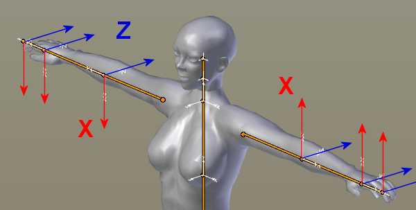
And also the local X axes are no longer aligned (and can no longer be aligned) to the global X axis which now runs in parallel to the outstretched arms. There is nothing entirely wrong with this. However we will see in the next lesson that this orientation shows a very bad behavior when you try to create symmetrical poses.
The Rules of Thumb
Actually the rig behaves much more convenient (as we will see) when we align all local Z axes of the arms to the global UP axis. And thus we end up with a generic and easy to remember set of rules:
- Horizontal Bones shall have their local Z axis aligned to the world’s UP axis.
- Vertical Bones shall have their local X axis aligned to the world’s sidewards axis.
- All other bones shall be treated either like horizontal or like vertical bones depending on their rotation angle in the global X-Y plane.
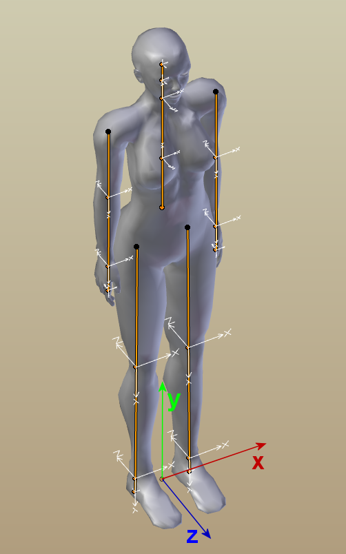
So, finally, after all rules are applied, then a BVH compatible human skeleton will have its arm bones aligned as follows:
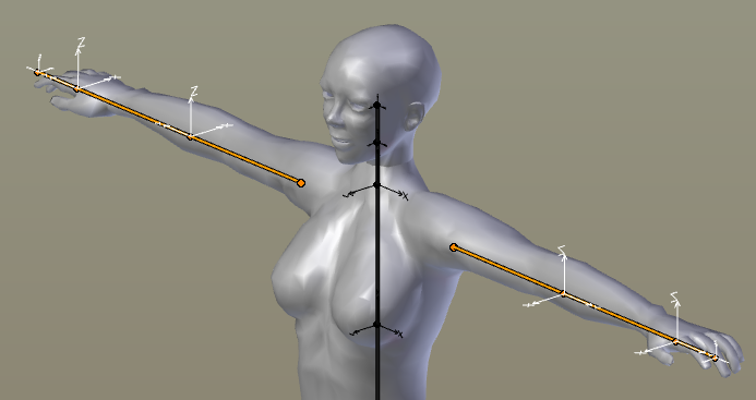
Click to Zoom in
And its leg bones have their local X axes all pointing to positive global X (as seen further up).
Actually we can reduce our rule of thumb to:
Tool conventions
Of course nothing is as easy as it could be. So one of the most apparent annoyances is that the 3D tools fall into two categories regarding their choice of the Global Up Axis. So lets see how the simple cube looks in Maya and in Blender for comparison. Do you see what i mean ?
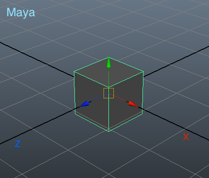

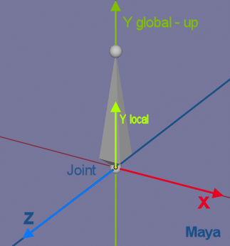
In Maya the global Y axis points up thus:
vertical bones:
- local X aligns to global X
- local Y aligns to global Y (UP)
- local Z aligns to global Z
horizontal bones:
- local X aligns to global Z
- local Y aligns to global X
- local Z aligns to global Y
In Blender the global Z axis points up thus:
vertical bones:
- local X aligns to global X
- local Y aligns to global Z (UP)
- local Z aligns to global Y
horizontal bones:
- local X aligns to global Y
- local Y aligns to global X
- local Z aligns to global Z

The only axis that matches with both program conventions is, as we can see, the X axis. Weird, huh? Please keep this in mind for later when we look at the Avastar Skeleton! However we see that Maya’s choice for the Global coordinate system is exactly compliant to what BVH imposes while Blender’s choice introduces a rotation of 90° around the global X axis.
I have added a chapter about Maya here. Although this is not strictly necessary to read, i still recommend you look at it. It may help you to understand the big picture
Maya in more detail
Maya in more detail
We want you to fully understand how a skeleton should be built in Blender. And how it has to be animated correctly without conflicting with Second Life’s animation engine assumptions. Therefore we will first do a really quick visit into some of Maya’s interface, Joints and Orientation. Then we will move on to Blender and see how we need to fix discrepancies that will arise from editing the skeleton.
Maya’s 3D viewport!
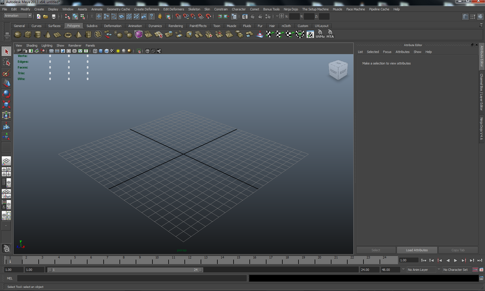
Click to enlarge.
Inspect a Bone
Let’s see what happens when we create a bone in Maya.
Do you notice something?
Yes, we see 2 “balls” at the tips of the bone. These balls are called Joints. But the interesting part is that both joints have separate coordinate axes. In Maya a bone is actually composed of two joints, whose respective axes by default do not need to match each other!
At the tail of the bone (the upper joint in the image) the axes actually follow Maya’s world orientation, but at the head of the bone (the lower joint in the image) the axes are oriented differently.
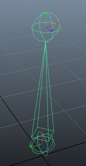
Maya bone with 2 Joints
However Maya allows custom bones/joints orientations to comply with any standard we might be working on, so we can make it fully compliant with the BVH standard orientation to achieve better cross-platform compatibility.
So the Linden Lab character developers decided to comply with Maya and BVH, foreseeing the animation uploads that Second Life currently allows. Equipped with this knowledge lets proceed by defining the SL Avatar Skeleton in Maya and start with the spine. When we keep the BVH definition and conventions in mind, then actually the construction of the SL Base skeleton becomes straight forward…
The Spine
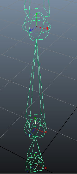
Since all bones of the spine point upwards, i will just align all joints to the world global orientation in Maya (Y). Thus for the spine all joints have all their local axes aligned to the corresponding global axes. Thus the bone’s longitudinal axes are naturally aligned to local Y (as imposed by BVH).
Look at the image… The image highlights the alignment of the joints to the world’s orientation which is upwards for the Spine. Please remind that the X-axes of all spine joints point sidewards and the Z-axes point forward (perfectly aligned to Maya’s global coordinate system).
The Arm- and Leg- chains
We will see that arms can’t have the same global orientation as the spine.
Remind: According to the BVH standards the Y axis of all bones always points along the Bones “from head to tail”. So, when the arms are being built, the first thing we need to check is that the local Y axis of the arm bones all point along the bone chain.
We will duplicate the Spine now to create the left arm chain…
The Arm Chains
After duplicating the Spine bones we interpret the new chain as the Avatar’s left arm. Hence we have to rotate them along Maya’s global Z-Axis by -90°, such that their local Y axes point from shoulder towards hands. When we look along the global Z-axis (front view in Maya), then we now see the new bone chain is oriented as follows with local X-axes pointing downwards and the Z-axes still pointing forward as before.
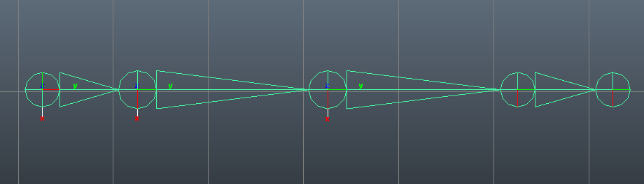
The Left arm (Shoulder on the left, Wrist on the right)
But according to the BVH conventions the local Z-axes of the arm bones actually have to point upward. Hence we need to rotate the chain by -90° along it’s Y-axis (so it will rotate along the longitudinal axis or “along itself”). Note this implies the local X axis will now point forward. This is the direction that the left arm’s joints must have according to the rules imposed by BVH (see above).
For the right arm all we have to do is duplicate the left arm and rotate the entire chain along its local z-axis by 180°. Thus for the right arm the local X-axes point backwards, again as imposed by BVH (see above)
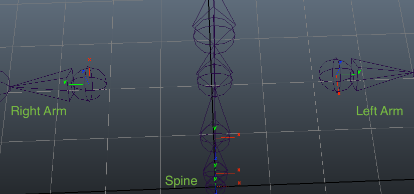
This is how spine and both arms should look. The apparent discrepancies between arms orientations has a benefit: This gives them the same relative orientation in animation, which helps us to copy poses from one side to the other. This happens because the Aim axis (the Y-axis that runs along the bones) points toward two opposite directions. So now the two chains rotate visually in the same direction when rotation values are added on their local X axis. I will give a practical example in the next chapter
Note: The Local Z-axes are still pointing up in both arms chains as implied by the conventions (see above)
The Leg Chains
Let’s take a look at the legs now.
Lets duplicate the spine again and rotate it by -180° on its local Z axis in order to have it pointing downwards and thus we construct our left leg. But since the basic concept behind this construction is to maintain Maya’s global axis directions, we see that the local X axis on this leg chain is now pointing in the opposite direction than the spine’s local X-axis.
So one more rotation is required, similar like we did for the arms, but now we have to rotate 180° around the local Y-Axis.
Note: Both leg chains actually get the same exact visual orientations, so there won’t be any difference between left and right, still their local Y-axis are pointing in the opposite direction that the spine does.
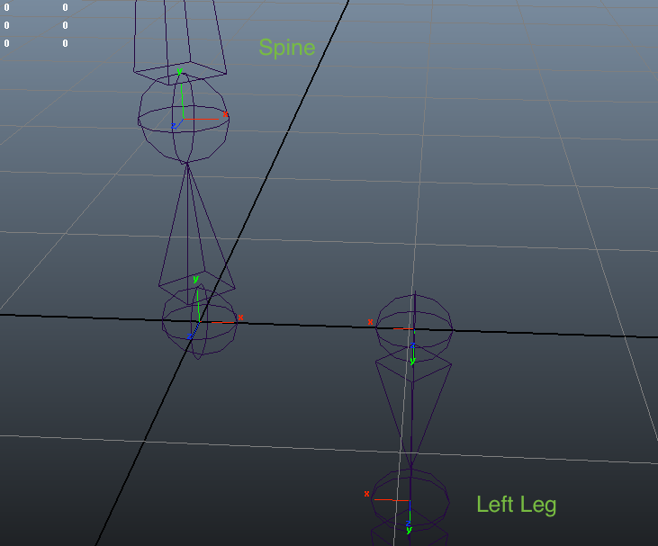
Left Leg: constructed from Spine and rotated by 180°
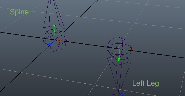
Left Leg: Final orientation of local X-Axis
Maya internal sidenote
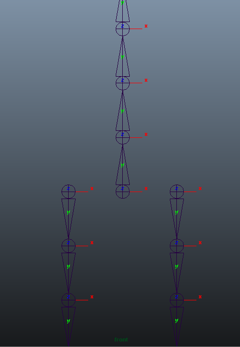
Connecting the Chains
Next i will show what happens when all these separate chains get connected in one single hierarchy skeleton…big surprise, we need an Outliner Window to do this!
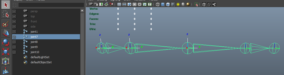
An even bigger surprise is what happens as soon as I put these two chains under the Torso joint in the hierarchy. A Link gets created in the 3D viewport to connect the parent Joint to these two children chains, exactly as we could see in Blender while preparing our Avastar for editing!

Proceed to Blender
Now that we have covered the basic concepts of BVH compliant skeleton building, it is time to move onto Blender and see what it gives us to work with for skeletons.
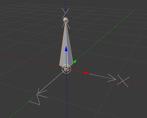
Adding a single bone
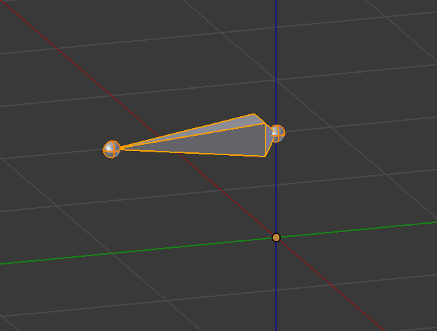
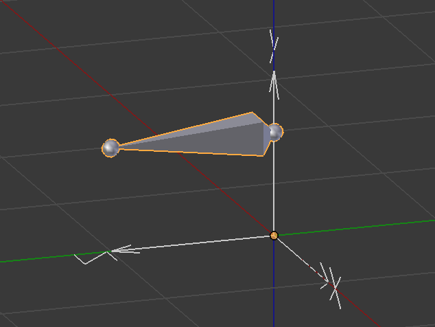
Once we open Blender, we can add a single bone from the Object Add menu to start building a skeleton. However this bone doesn’t show any directional arrows to us. All we get is the manipulator widget to move the entire object around (i added the X-Y-Z characters manually by editing the image).
But we activate the axes visibility in order to see the bone orientation in global space.

Show Bone Axes in Object Mode
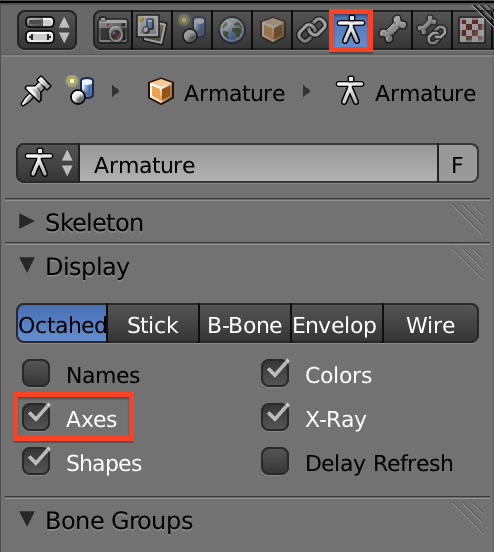
There is an “Axis” Property in the Armature’s Object Properties Window (Cube Icon). Locate the Display panel, and enable Axis to show the local bone axis of the armature. As soon as the property is enabled, we see something like this as long as we are in Object Mode:
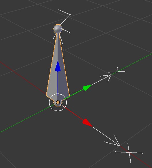
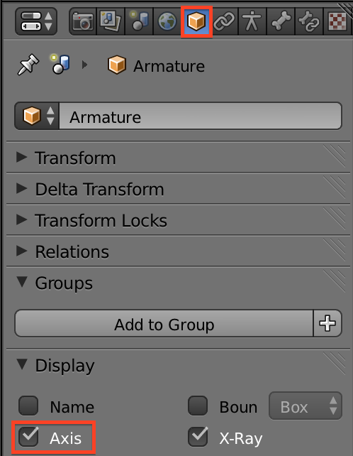
Now the X-Y-Z axes are automatically displayed by Blender. Those extra arrows point along the same directions as our manipulator. This means that the bone’s local coordinate system is fully aligned to Blender’s global coordinates, with Z up.
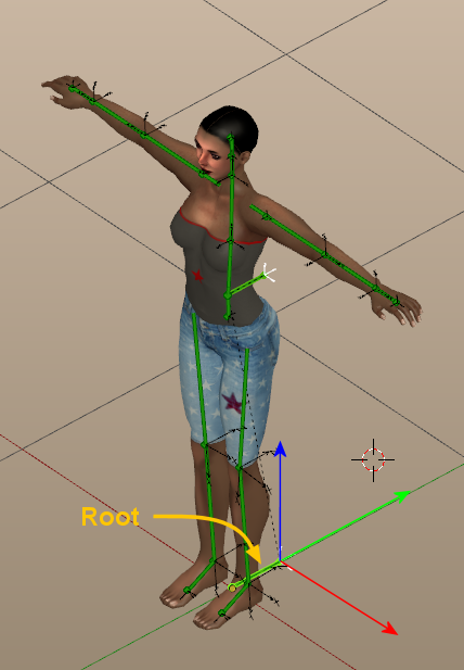
The Root Bone
Skeletons in Blender are always created as a bone hierarchy with the first created Bone at the root. This first bone of our Rig is also named the Root Bone. Actually the Root Bone builds a bridge between the skeleton coordinates and the scene coordinates. Thus the local orientation of the entire rig is defined by the root bone.
The entire rest of the skeleton will be built with this bone at the top in the bone hierarchy, and most important:
BVH again …
The Root Bone is actually also used as the world reference when exporting this armature’s animations as a BVH file. So all animations will be recorded relative to the root bone and not relative to the Global Space.
We can make our Rig compatible with the BVH standards by aligning this “first bone of the rig” to the correct reference, which was Y up and Z forward.
Actually we only need to rotate the bone in Object mode by 90° along the X-axis. Then the Bone coordinate System is aligned to the same axis orientation as we need to comply with BVH. ( Y Up, Z Forward, X Right)
A good idea, but…
Now we could let the Bone’s tail point upward again to get the first spine bone for example. You can do this in edit mode. The easiest method is:
- Select the Bone Head
- Snap cursor to selected
- ensure your pivot is set to 3D Cursor
- Select the Bone body
- Rotate by -90° around the X axis.
That looks perfect… But…
We see, this method actually would work but it is a very week construction and has to be used very carefully. Also we will see in a short while that trying to force Blender to work with a rotated root bone can lead to some confusion. However we can avoid all of this entirely and let Avastar do the job instead…
Avastar’s Origin Bone
When we look closer at the Root Bone, we see that it is aligned exactly as we decribed above (longitudinal bone axis aligned along Global Y)
btw: The root bone is not necessarily a member of the actual deforming skeleton, so it normally can be aligned in Blender however it makes sense for your task.

So you can see the Root bone as a handle for placing a character into the scene. For the sake of ease it makes also a lot of sense to align the root bone to the scene’s global coordinate system…
The Avastar BVH Exporter knows about the global axes of Blender and it knows about what BVH actually wants to see. So the exporter calculates the rotation that is needed to get the root bone imported laying flat on ground in a Y-Up target system. All other bones of the rig will follow this rotation.
Even when the character is oriented in an arbitrary position and when this bone is rotated in Blender’s global space, the BVH exporter still can recalculate how the skeleton has to be exported to propagate this rotation into the target system.
Sounds too complicated to you ? Don’t worry. All you have to do is:
- Take care that your character looks towards Blender’s negative global Y axis when in Rest Pose
- Ensure that the Origin bone is aligned to the global Blender axes in Rest Pose.
- Once these settings have been set, you can rotate (in Object mode) your character in global space as you like.
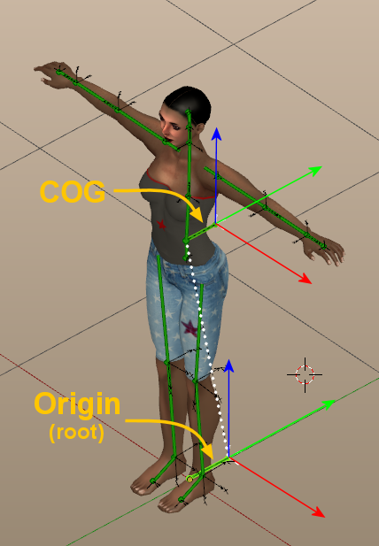
The COG Bone
In Avastar we actually used a “secondary Root Rone”, the COG Bone:
The COG Bone is the immediate child of the Origin. The COG (Center of Gravity) is the “inner root” of the exported animation. thus it controls the movement of the character relative to the Origin. The Avastar BVH exporter actually uses the Origin to determine the Armature’s orientation in Global Space and it uses the COG Bone to animate the location and rotation of the character.
Note: The COG Bone’s local axes and the Origin’s local axes are oriented in the exact same rotation (local Y points backwards) But while it is mandatory for the Origin, the COG can be reoriented as you like (as you need).
Before we proceed to our Horse model, let us first take a more detailed look into Bone editing.
Editing the Bone(s)
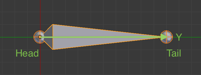
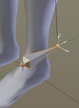
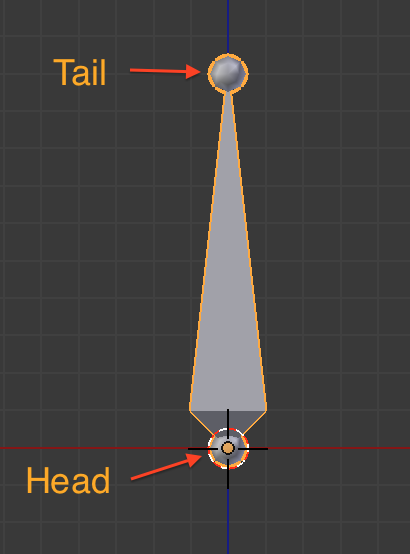
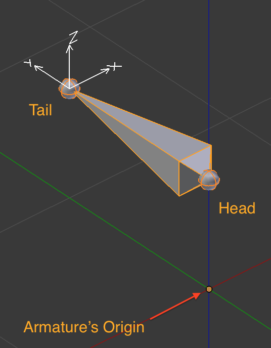
The rest of the work now has to be made in Edit mode. In this mode we can duplicate, parent, unparent, move, scale and fix the bones individually, moving around those two little spheres at either ends of the bone.
Those two spheres are called in Blender respectively Head (larger side of this bone) and Tail (its thinner tip).
We need to take care of several aspects to get a consistent rig that behaves well and makes our life as easy as possible when we later work on our animations. So lets go ahead and let’s tab into Edit mode…:
Bone Edit Mode
We notice that in Edit mode the Armature’s local coordinate system disappeares. That’s because it refers to the Object orientation, while in Edit mode we are modifying the ingredients of the Armature Object (the Bones).
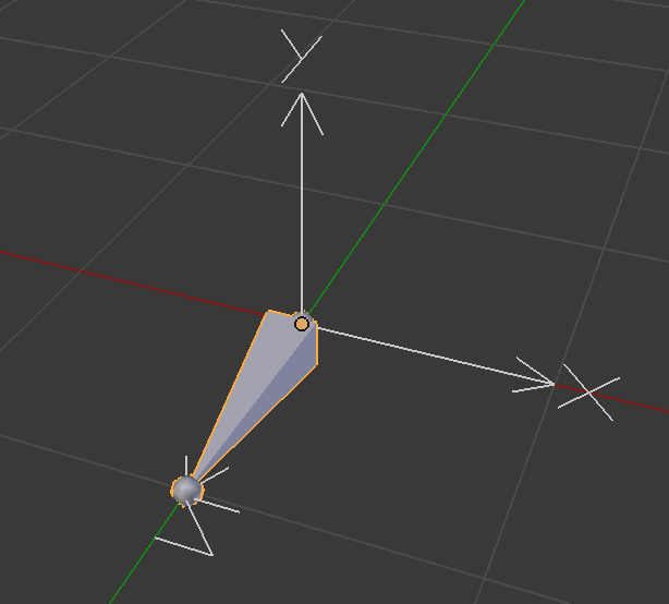
So, while still in edit mode, let’s move this bone a bit upwards. Notice the object’s origin (pinkish dot) did not change its location.
When we now switch back to Object mode we see that the object (and its coordinate system) is still where it was before, we just moved the location of the bone relative to the armature object without changing the Armature’s global position in 3D space.
Note: While this edit is not “wrong”, you should keep the Root Bone’s head located at the Armature’s Origin just to have a clean setup.
Local Bone axes
Actually each bone has its own local coordinate system, which defines a location (the Bone offset) relative to the Armature’s Origin and a relative rotation around its local Y axis(the Bone Roll) .
While the location can be modified easily (by using the translation operator (‘g’ as we have shown above) the Bone Roll has to be edited in a different way. We will see in the next chapter how to change the Bone Roll as needed.
Bone Axes in Pose/Edit Mode
For viewing the Bone local axes we need to activate another checkbox, this time in a different section of the Property panel:
Click on the Object Data Tab, which turns its icon into a stickman figure when a skeleton is selected. In this Tab locate the Display Panel (as we did before in the Object Tab) and tick on the “Axes” Checkbox.
Now we see (while we are in Edit mode or Pose mode) those directional x-y-z arrows appearing at the bone’s tail. Those axes are what defines the Bone Roll, which should be compliant to BVH.
In Blender the local Y axis of a bone always points along the bone from Head to Tail. While the bone roll is actually defined as a rotation of the bone’s local X-Z plane around the Y axis.
Bone Transform Properties
Remind that we have rotated the Origin before by 90° along X, hence the local x-y-z data in edit mode is stored different form what you might expect.
Lets see what i mean and take a look at the Bone’s Transform Properties. You find these in the Properties sidebar of the 3D View (Press ‘n’ if the sidebar is currently hidden)
Blender actually stores the locations of the Head and the Tail of each bone relative to its parent bone. In our case the Bone is the root bone, thus it has no parents, thus its local Transform data is stored relative to the Object’s Origin.
Transformations In Edit Mode
For example: In our case the Bone has been lifted along Blender’s global Z-Axis (The armature’s local Y axis, see upper image on the right), and in edit mode we see that the Head and Tail are apparently lifted along the Objects Local Y-Axis! (see lower image on the right)
Actually this is another reason why you should not rotate the root bone in Object mode for trying to align the Armature axes according to the BVH standards (and run into confusions like this).

Editing Bone Roll
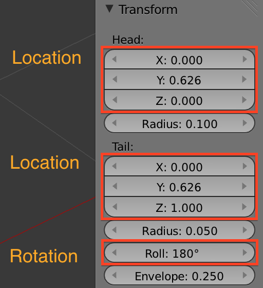
You find the Bone Roll value below the Tail location. Please take a moment and modify the Bone roll manually to see how the local x-y-z axes rotate relative to this Value.
You also can change the bone roll (in Edit mode) by using the keyboard Shortcut CTRL+R Then you can rotate the current selected bones all at once by the same amount of rotation. or you can type in a specific rotation value on the keyboard while in this mode.
We will talk more about Bone Roll in the next lesson.
The Bone Data Properties
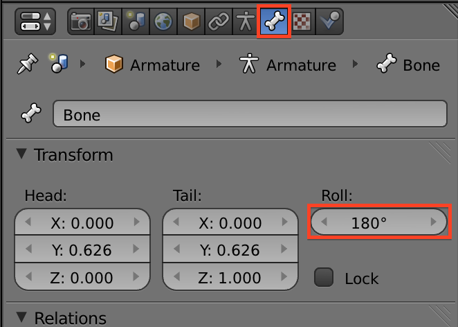
To complete this part i want to take a brief look into the Bone Data Properties Tab as well (The one with the Bone Icon)
This is an alternative window where you can find the Transform Properties of your Bones:
- Head Location (relative to Parent Bone
- Tail Location (relative to Parent Bone)
- Bone Roll (along bone’s longitudinal axis)
Summary
Now that we’ve got these things to show, we can build our own skeleton. However we will see that the editing process might disrupt the bone rolls. So, while you work on your custom rig, you need to pay attention to Bone Roll and to the single bones’ orientation when you’re done editing it.
This is exactly what we need to take care of when editing an already made rig of any sort (SL avatar included) to fit a different shape:
Also note that your custom character most probably will need of a custom AnimationOverrider to work correctly in SL. This becomes more apparent the farther away the character’s shape gets from the human shape. For example the horse avatar that we will build next will look very weird (crossing its front legs in a very unnatural way) when we play the default animations on it. Well, this is not a big surprise because the default animations have actually been designed for an antropomorphic character.
And because the correct setup of the rig is so extremely important we have added another lesson where you learn how to set the Bone Roll Values in a meaningful way.
Preview on next lesson
Bone rolls values are extremely important to let the rig work correctly during animation. Having a clean and consistent bone setup with correct bone roll settings also avoid tedious and sometimes almost impossible fixes.
The correct bone roll settings are also important for animators because one of the major interaction models for transforms is via hotkeys, using the x, y, and z keys to specify axes. And finally a well organized setting of bone roll can make manual animating easier when we use Blender’s pose tools for copy&paste and copy&mirrorpaste…
luckyland slots app: Free coins today, big rewards tomorrow! Join for 7,777 Gold Coins + 10 Sweeps Coins right now. Spin thrilling games and cash in your Sweeps!