SLS-6 Bone Transformations
Free PreviewBones and Joints
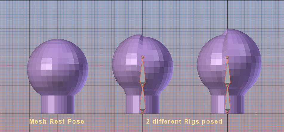
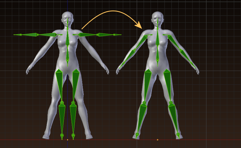
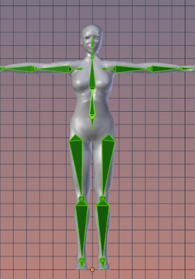
In the following image all meshes have exactly the same weight maps and exactly the same rest pose (indicated on the left side). Can you predict the difference between the rig in the middle and the rig on the right side?
In order to understand what happens here we have to step back for a moment to the beginning of the previous chapter where i mentioned:
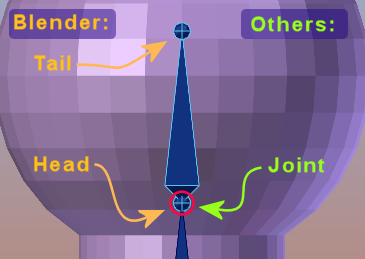
in Blender we have Bones with Heads and Tails. While in other tools we only have Joints where Joints are mostly equivalent to Bone Heads: they both define the location of pivot points. Unfortunately the terms Joint and Bone are often used interchangeably, which can lead to confusion at times (see further down).
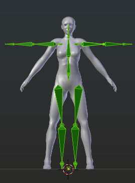
Lets take a look at the entire Skeleton. The red dots in the images below mark the Joint positions of the SL Skeleton. On the left side you also can see the Blender Bones marked in green.
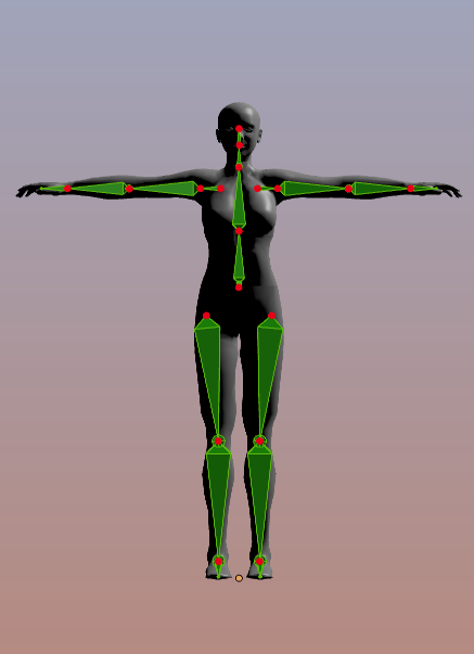
Blender uses Bones (displayed in green here)
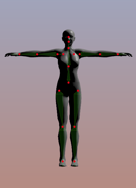
Other tools use Joints (Displayed as red dots)
Here is the proof: The Bones on both sides have different lengths. However the Joints on the right side and on the left side are at the same locations, hence the Bone transformations get applied to the Mesh in the same way. Hence both meshes get influenced in the same way. Conclusion: The length of the Bones is not taken into account.
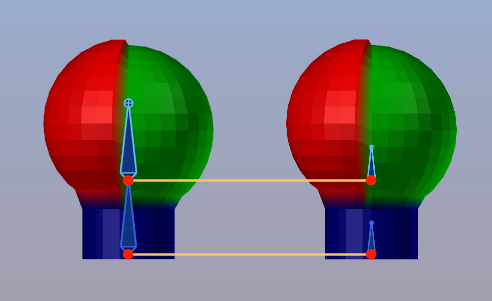
In Blender bone lengths do not affect skeletal animation
Move and Scale
So lets get back to our simple example and lets look at it in more detail:
Hence we see the left part of the mesh raise higher. But because we only used Translation here, the spherical shape keeps intact on both sides.
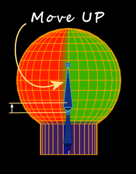
mHead in Rest pose. When moved upwards only the mNeck Joint stays at its place.
But the scaling of the lower bone also influences the Joint position of the upper bone. So scaling the lower bone moves the upper bone upwards. And since the upper bone is weighted to the mesh as well, it tears the mesh along with it.
So, although i only scaled the lower bone, the mesh bends according to both Joint matrices on behalf of both weight maps.
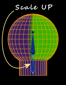
mNeck in Rest pose. When scaled up also mHead gets pushed upwards, thus both Joints change.
Now you also understand why both Rigs look equal (having bones of same length) but influence the mesh differently (as you can see on the differences in the shape).
From the simple examples above you already can see how complex a skeletal animation can become when more than one bone (more than 1 weight per vertex) is involved.
A small excursion to Bone names
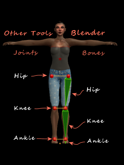
Did you ever wonder about the names of the SL Character’s bones ? And you had the impression something is wrong ? Open your Blender and look at the leg bones for example. There you find:
- Hip
- Knee
- Ankle
Now compare this to what you might see in Maya for example (ok, it is enough to look at the image aside). In Blender’s system (on the right) we see the bone names are a bit unclear. But when you take the names for the Joints (on the Left), then suddenly all names make a lot of sense. BTW: The same is true for the Arm bones:
- Collar
- Shoulder
- Elbow
- Wrist
What you see here is just the result of small incompatibilities introduced by different software solutions. And we (the users) have to live with this. However, for Blender Users it should have become crystal clear by now that we only need to take care about Bone Heads and we mostly can ignore Bone Tails.
The Bind Pose
Ok, now after all… Lets do something. Let’s say you have a skeleton and you have a mesh that shall be controlled by the skeleton. Right now they are separate and do not know anything about each other. However, your 3D Tool provides a function for associating the mesh to the skeleton. This is typically named Binding (the mesh to the skeleton) and the Pose that was used on the Skeleton at the time when the mesh was bound to the Skeleton is named The Bind Pose.
And it is this Bind Pose where the Skeleton will keep the Mesh completely unchanged, regardless of what is written in the weight maps of the mesh and regardless how the Joint Transformations are defined:
The Rest Pose
Assume you have reset all transformations in all Joints, so all rotations are set to 0, all scales are set to 1.0 and all location offsets (translations) have been reset to 0. Then your Skeleton is in Rest Pose. This name was chosen to express that all Joint transformations are neutral. However, the rest pose is just another pose like all others. So it also can be used when binding the Mesh to the Skeleton and there is nothing special about it.
Blender, we have a problem!
As i explained above, you would normally pose your Skeleton such that it matches your mesh as good as possible. And when the match is good enough, then you would bind your mesh to the current Pose. But in Blender we have no other option than to put the Skeleton into Rest Pose, then adapt our mesh to the Skeleton and then Bind the mesh to the rest pose.
Blender can only Bind a mesh to Rest Pose. If the Mesh is in a different Pose, then we get a problem.
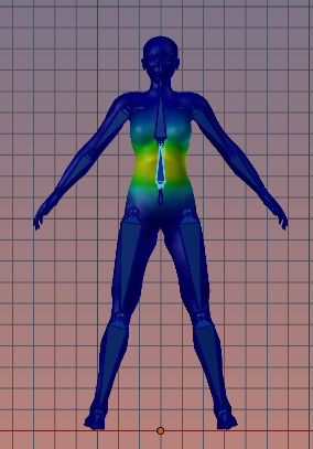
One perfect example for where we get into a serious problem is when our mesh model was created in A-Pose. In that case (see image above), we have to do quiet a bit of tweaking before things get nice.
Another example is the “Poncho problem”. A Poncho works best in a stand pose. So it would be awesome if we could use the stand pose for binding the mesh. But in Blender we can not do that, we have to rig the Poncho in Rest Pose. And the SL Rest Pose is with arms stuck straight sideways.
However, there is a workaround for rigging a mesh in an arbitrary pose:
Blender: Rigging a Mesh in A-Pose
Normally you would pose the Rig such that it matches as good as possible to the Mesh, then simply Bind the Mesh to the current pose (the Bind pose) as explained above. The tool would then know this is the pose where all bone influences on the mesh are zero.
But in Blender we do not have a Bind Pose and all meshes must be bound to the Rig in Rest Pose. Hence we need to use a little trick. I will use a Mesh in A Pose as a demo. Here is the workflow:
1.) Adjust the Rest Pose to the Mesh
The Rest Pose of the SL Avatar is the T-Pose (as seen on the left side of the image below). In the background behind the Skeleton you see the Mesh in A-Pose. This mesh is not yet rigged, nor is it weighted.
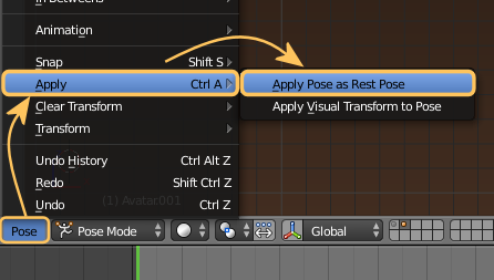
Now we pose the Skeleton bones to match the Mesh as good as possible (as seen on the right side of the image below):
Pose -> Apply -> Apply Pose as Rest Pose
By now we have changed the Skeleton’s Rest Pose to match the A-Pose of the Mesh. So when you now reset your pose ( Pose -> Clear Transform -> All) then it will go into A-Pose and no longer into T-Pose as before (So the Rigs Rest Pose is now the A-Pose)
We are now ready to …
2.) Bind the Mesh to the Armature
Binding the Mesh to the Armature is now again straight forward. Blender allows us to even add some initial weights to our character during binding. We do this as follows:
- Ensure the Armature is in Object mode
- Select the Mesh (RMB)
- Add the Armature to the selection (SHIFT RMB)
- Object -> Parent -> With Automatic Weights
Now you have your mesh rigged and weighted. You may now want to optimize your weights until the mesh works nicely for your animations.
However you do not need to use any tricks here and you can adjust your weights using all Blender standard weight tools. However always remind that you no longer work with a T-Pose rig! So when you later want to get your Mesh into Second Life you have to perform a couple of additional steps:
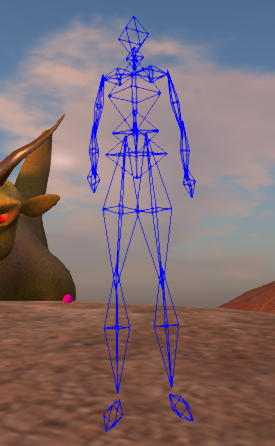
3.) Get back to T-Pose
Hint: You can create (append/Link) another Second Life Rig which is in the default T-Pose and use that as guideline for posing your A-Pose Rig.
When we are done with posing the Character into T-Pose, we next will…:
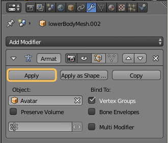
4.) Apply the Armature Modifier
- Ensure your armature Pose matches the original Avatar’s T-Pose as close as possible.
- Then Select the Mesh(!)
- And open its Modifier Stack.
- Locate the Armature Modifier
- While in Object mode, apply the modifier
By now we have a Mesh in T-Pose with all its weight maps intact, but the mesh is no longer rigged. We can now either revert the changes in our Rig (reverts its Rest Pose to a T-Pose) , or we can just load a fresh version of the SL Skeleton (from the Avatar Workbench for example). Lets save our Mesh into a blend file, open a new Workbench and Link (or Append) our mesh, Then …
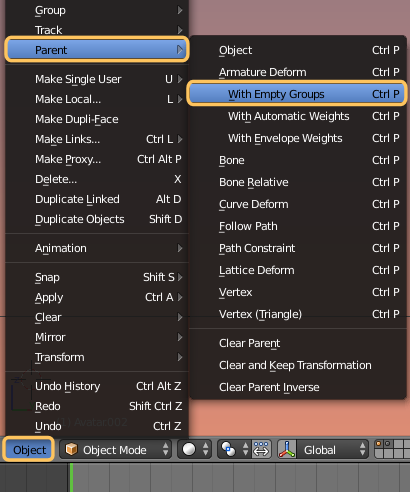
5.) Rig the Mesh to the SL Skeleton
Now we are on the safe side. Our Mesh IS in T-Pose and it even has all its weights already assigned and working nicely as intended. So all we now have to do is parenting the Mesh to the T Posed SL Skeleton.
- Ensure you use an Armature that has a T-Pose as Rest Pose.
- Select your Mesh in Object Mode (RMB)
- Then add the Armature (SHIFT RMB)
- Object -> Parent -> With Empty Groups
This ensures that your already existing Weight Groups are preserved.
Now you have rigged your Item perfectly to the Second Life Skeleton. We can export it and be happy … (hopefully)
Separation of concerns: Shaping and Animating
By now we have repeatedly seen how complex the Joint Transformations of a Rig can become. So it is time to introduce some simplification rules and best practices to keep your animated meshes under control. And the very first simplification is about separating Animating and shaping the Meshes:
Shaping
Shaping means basically: modify the volume of the meshes. This is primary done by using the Joint Scaling, but also by moving the Joint offsets around. So you can change the size and volume of your mesh by using the Translation-part and the Scale-part of the Joint Transformations.
This is exactly what the “Bone Changing Sliders” do in the Avatar Appearance Editor in SL.
Animating
Animating means basically: move the character around in space. This is typically done by using only the Rotation-part of the Joint Transformations. However you might wonder how your character can get moved around in the virtual environment with only rotating its bones.
Well, there is one Bone that is used to get the entire character moved around: the Root bone. And in fact the root bone is used only for this purpose!
We all have heard advices like “do not use Translations and Scale in your SL animations”. And some might have realized that rotations are not used when you modify your Shape in the Appearance editor. And now i hope that you just got your first light bulb flashing up bright and you see now why things as they are.
Interaction with Environment (Collision Volumes)
A character not only moves around in the 3D environment (in Second Life), but it also bumps into other objects (walls, other characters, …) during its travel in virtual space. So how is that “done” after all ?
This is where the Collision Volume Bones step in. These bones are part of the Second Life skeleton. Actually we have 19 primary Collision Volumes which are clamped to the SL Deform bones (the mBones). Remind that the Deform Bones are the ones which are weighted and which control the mesh transformations.
Each Collision Volume Bone has a specific Scale Value which defines its volume (size). And each Collision volume controls the size of a simple octahedral mesh (see image). These simple meshes are used as an approximation of the SL Avatar.
This extremely simple approximation of the SL character is used for very fast calculation of when a character bumps into an object (or another character). Actually the calculator only needs to take into account 6 vertices per Collision Volume (114 vertices for the entire character) to get a rough estimate for when the character bumps into something else.
Can all bones be weighted ?
Now this is a good question. By now we know that there is a specific set of Deform bones which are meant to be weighted: the 21 mBones (plus 5 extra bones mSkull, mEyeLeft, mEyeRight, mToeLeft, mToeRight) But bones are just bones, hence in principle any bone can be used as Deform Bone. Hence any bone can be weighted, even Attachment Bones and Collision Volume Bones.
By now the second light bulb should start to glow in your mind (hint: Weighting of the Collision Volume Bones is what we know as Fitted Mesh)